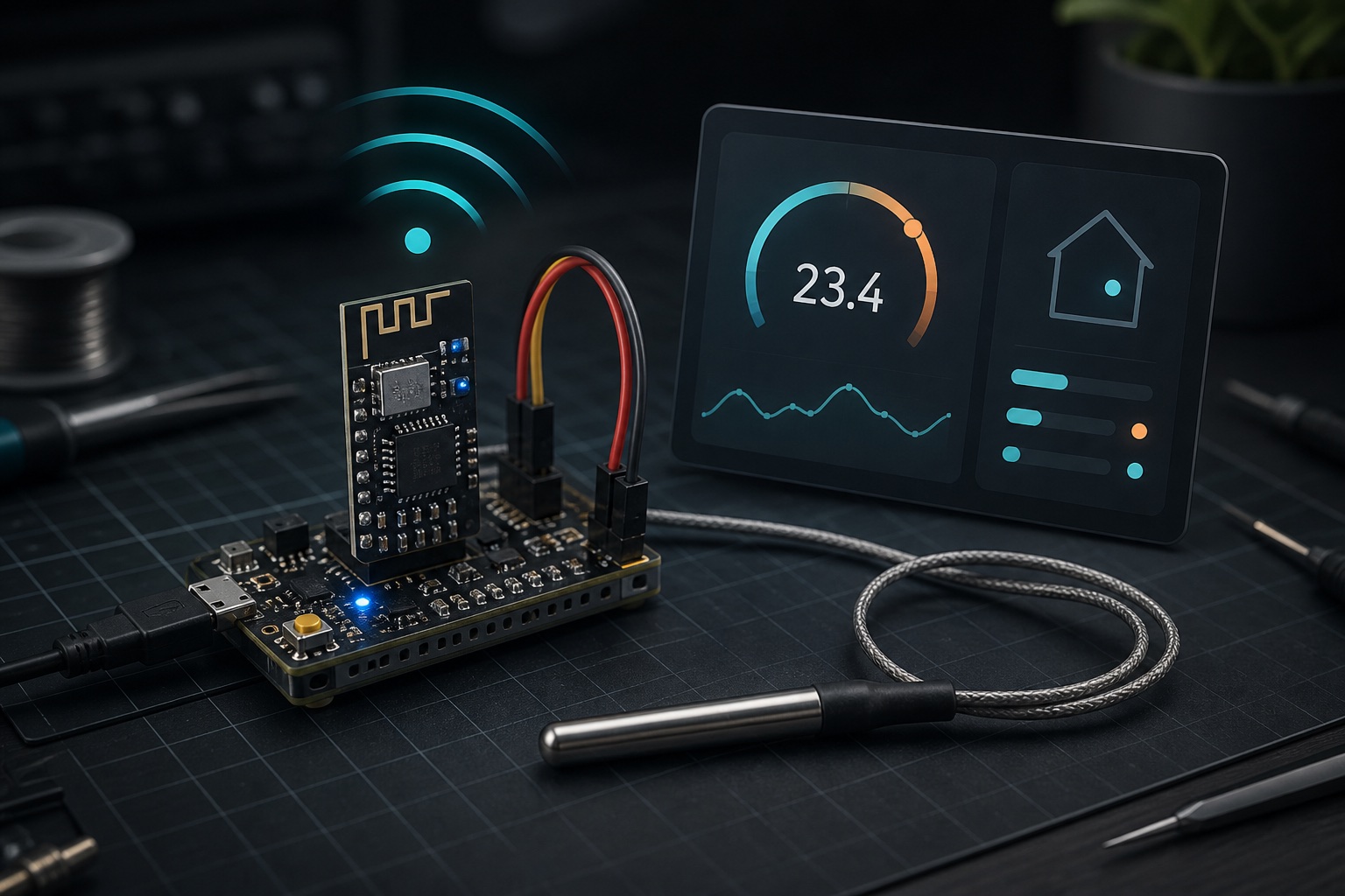
Build a Wi-Fi Temperature Monitor with an ESP-01
The ESP-01 is one of the smallest ways to add Wi-Fi to a project. It contains an ESP8266, a small amount of flash, and just enough exposed pins to build useful connected devices. Its limited pin count makes it less convenient than a NodeMCU for prototyping, but it is inexpensive and easy to hide inside a small enclosure.
In this project, an ESP-01 reads a DS18B20 digital temperature sensor and serves the result over the local network. Open its IP address in any browser to check a room, refrigerator, network cabinet, aquarium, or greenhouse. No cloud account, mobile application, or external server is required.
What we are building
The finished device provides two local endpoints:
/shows a small dashboard that refreshes every five seconds./temperaturereturns JSON for another application or home-automation tool.
The browser talks directly to the ESP-01:
DS18B20 ──GPIO2── ESP-01 ──Wi-Fi── Phone or computer
                                     ├── /             dashboard
                                     └── /temperature  JSON
This is intentionally a small project. It teaches the parts that make many IoT devices work: reading a sensor, joining Wi-Fi, exposing data over HTTP, and handling a disconnected sensor.
Parts
- ESP-01 or ESP-01S module
- DS18B20 temperature sensor
- 4.7 kΩ resistor
- Regulated 3.3 V supply capable of at least 500 mA
- 100 µF and 0.1 µF capacitors for supply decoupling
- 3.3 V USB-to-serial adapter for programming
- Breadboard and jumper wires
Use a three-wire DS18B20 connection rather than parasite power. Bare TO-92 sensors and waterproof probes use the same protocol, but probe wire colors are not guaranteed. Check the seller’s datasheet before connecting one.
Wire the sensor and ESP-01
Connect the circuit as follows:
| ESP-01 / supply | Connect to |
|---|---|
VCC |
Regulated 3.3 V |
GND |
Ground |
EN / CH_PD |
3.3 V |
GPIO2 |
DS18B20 data pin |
| 3.3 V | DS18B20 VDD pin |
| Ground | DS18B20 GND pin |
Place the 4.7 kΩ resistor between GPIO2 and 3.3 V. Put the 100 µF and
0.1 µF capacitors across 3.3 V and ground, close to the ESP-01.
GPIO2 is a boot-strapping pin and must be high when the ESP8266 starts. The sensor’s pull-up resistor keeps it in the correct state. Avoid adding anything that pulls GPIO2 low during reset.
The ESP-01 is a 3.3 V device. Do not connect its VCC or GPIO pins to 5 V. Wi-Fi transmission causes short current spikes, so the 3.3 V output on some USB-to-serial adapters is not a reliable power supply.
Prepare the Arduino IDE
Install ESP8266 board support in Arduino IDE, then select Generic ESP8266 Module. From Library Manager, install these two libraries:
OneWireby Paul StoffregenDallasTemperatureby Miles Burton
Create a new sketch and replace YOUR_WIFI_NAME and YOUR_WIFI_PASSWORD in the
following code:
#include <ESP8266WiFi.h>
#include <ESP8266WebServer.h>
#include <OneWire.h>
#include <DallasTemperature.h>
const char* WIFI_SSID = "YOUR_WIFI_NAME";
const char* WIFI_PASSWORD = "YOUR_WIFI_PASSWORD";
constexpr uint8_t ONE_WIRE_PIN = 2; // ESP-01 GPIO2
OneWire oneWire(ONE_WIRE_PIN);
DallasTemperature sensors(&oneWire);
ESP8266WebServer server(80);
float readTemperatureC() {
sensors.requestTemperatures();
return sensors.getTempCByIndex(0);
}
void sendDashboard() {
const char page[] PROGMEM = R"HTML(
<!doctype html>
<html lang="en">
<head>
<meta charset="utf-8">
<meta name="viewport" content="width=device-width,initial-scale=1">
<title>Room temperature</title>
<style>
body { font: 18px system-ui; margin: 0; display: grid; min-height: 100vh;
place-items: center; background: #eef2f6; color: #17202a; }
main { text-align: center; background: white; padding: 2.5rem;
border-radius: 1rem; box-shadow: 0 8px 30px #0002; }
#value { font-size: 4rem; font-weight: 700; margin: .5rem; }
#status { color: #5d6d7e; }
</style>
</head>
<body>
<main>
<h1>Temperature</h1>
<p id="value">--.- °C</p>
<p id="status">Reading sensor...</p>
</main>
<script>
async function update() {
try {
const response = await fetch('/temperature', { cache: 'no-store' });
if (!response.ok) throw new Error('Sensor unavailable');
const data = await response.json();
document.querySelector('#value').textContent =
`${data.celsius.toFixed(1)} °C`;
document.querySelector('#status').textContent = 'Updated just now';
} catch (error) {
document.querySelector('#status').textContent = error.message;
}
}
update();
setInterval(update, 5000);
</script>
</body>
</html>
)HTML";
server.send_P(200, "text/html; charset=utf-8", page);
}
void sendTemperature() {
const float temperature = readTemperatureC();
if (temperature == DEVICE_DISCONNECTED_C) {
server.send(503, "application/json", "{\"error\":\"sensor disconnected\"}");
return;
}
const String json =
"{\"celsius\":" + String(temperature, 2) +
",\"fahrenheit\":" + String(temperature * 1.8f + 32.0f, 2) + "}";
server.send(200, "application/json", json);
}
void setup() {
Serial.begin(115200);
sensors.begin();
WiFi.mode(WIFI_STA);
WiFi.begin(WIFI_SSID, WIFI_PASSWORD);
Serial.print("Connecting");
while (WiFi.status() != WL_CONNECTED) {
delay(500);
Serial.print('.');
}
Serial.println();
Serial.print("Open http://");
Serial.println(WiFi.localIP());
server.on("/", HTTP_GET, sendDashboard);
server.on("/temperature", HTTP_GET, sendTemperature);
server.onNotFound([]() {
server.send(404, "text/plain", "Not found");
});
server.begin();
}
void loop() {
server.handleClient();
}
The HTML lives in flash through PROGMEM, preserving the ESP8266’s limited
working memory. The temperature endpoint returns both common units, so a client
can use the data without repeating the conversion.
Upload the sketch
Disconnect the sensor while programming if that makes the header easier to reach. Connect the USB-to-serial adapter with crossed serial lines:
- Adapter TX to ESP-01 RX
- Adapter RX to ESP-01 TX
- Adapter ground to ESP-01 ground
- The regulated 3.3 V supply to ESP-01 VCC and EN
To enter the bootloader, connect GPIO0 to ground and then power or reset the module. Upload the sketch. After the upload completes, remove the GPIO0-to-ground connection and reset the module again so it starts normally.
Open Serial Monitor at 115200 baud. Once connected, the ESP-01 prints an address
similar to http://192.168.1.42. Open that address from a device on the same
Wi-Fi network.
To see the machine-readable response, open /temperature:
{"celsius":23.56,"fahrenheit":74.41}
Make the address easier to find
The router may give the ESP-01 a different IP address after a restart. The most
reliable fix is a DHCP reservation in the router: reserve an address for the
MAC address printed by WiFi.macAddress().
This is preferable to hard-coding an address in the sketch because the router remains the source of truth and can prevent address conflicts.
Troubleshooting
The module repeatedly resets
The usual cause is weak 3.3 V power. Use a proper regulator, keep the wires short, add the decoupling capacitors, and make sure all components share ground.
Uploading fails
Confirm that GPIO0 was low during reset, TX and RX are crossed, the adapter uses 3.3 V logic, and no other program has the serial port open. Lowering the upload speed can help with long or poor-quality wires.
The API reports that the sensor is disconnected
Check the DS18B20 pinout, common ground, and 4.7 kΩ pull-up. A genuine reading of
-127 °C from the DallasTemperature library indicates a communication failure,
not an extremely cold room.
The module runs only while connected to the programmer
Make sure EN is held at 3.3 V and GPIO0 is no longer grounded. GPIO0 low at reset selects the serial bootloader instead of the uploaded application.
Useful next steps
This small server is a good base for a larger project. You could:
- Add a warning color when a refrigerator becomes too warm.
- Poll the JSON endpoint from Home Assistant, Node-RED, or a small dashboard.
- Store periodic readings on another computer to draw a history chart.
- Add a second DS18B20 on the same data wire and read each sensor by address.
- Put the circuit in a ventilated enclosure with a USB-powered 3.3 V regulator.
Keep the device on a trusted local network. This example has no login or TLS, so do not forward port 80 from the internet. If remote access is needed, connect to the home network through a VPN or let an authenticated home-automation system relay the data.
Takeaways
The ESP-01 looks constrained, but one GPIO and a tiny HTTP server are enough for a useful device. The DS18B20’s single-wire interface leaves the circuit simple, and its pull-up also satisfies GPIO2’s boot requirement. With stable 3.3 V power, the result can run quietly on a shelf and make its measurements available to every browser on the local network.